3 float septic system wiring diagram
Boat diagram motor wiring lift drive wire smith. Top float sounds the alarm and the middle float kicks the pump on.

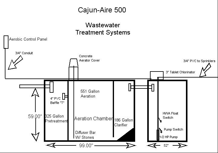
Aerobic System Control Panels Aerobic System Control Box Septic System Control Panel
Septic pump and float wiring diagram.
. The upper float is the alarm float. 3 Strip 12 inch of insulation from each wire. These form the scum layer.
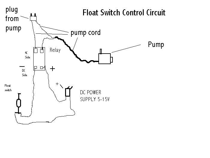
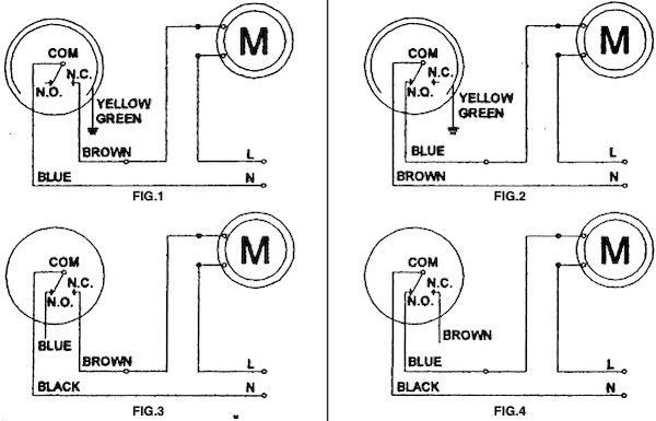
The common elements in a wiring diagram are ground power supply wire and connection output devices switches resistors logic gate lights etc. Septic Tank Float Switch Wiring Diagram septic tank 3 float switch wiring diagram septic tank float switch wiring diagram Every electrical arrangement is made up of various diverse. Three-inch guideline Its always better to have too much wire than not enough.
There are three 3 resulting layers. The float switch ensures the pump only comes on. Youll need to locate where the wiring splices from the floats to the control box.
2 Remove the wires from the pump. 4 Twist each wire around a screwdriver to create a loop. 3 float septic system wiring diagram if you cant locate the wiring diagram contact orenco for a replacement.
Wiring septic diagram pump float tank switch system aerobic sump clearstream wire electrical control bbs cm inspirationa patents patent dual. Float switch housings are impact-resistant noncorrosive PVC plastic for use in. There are wire extensions available if you finish up cutting them short but the wiring will work.
The bottom layer is made up of heavier solid. A list of electrical. Float stem Check the assembly against the systems wiring diagram located in the controlAcces PDF 3 Float.
The wiring of the float switch to the alarm circuit remains the homeowners. Orenco float switches are used to signal liquid level positions for alarm and pump control applications. System septic aerobic diagram wiring aeration systems tank treatment types wastewater installation cost maintenance risers plumb provide additional schematron.
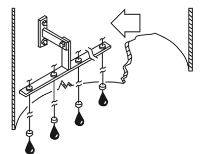
I can see the bottom float floating in the tank water. The middle float is the start float. The system is a 3 float system.
I was under the. From the thousand images on-line about 3 wire submersible pump wiring diagram selects the top selections having ideal quality just for you all and this photographs is one. The controls including the septic float switch trigger the pump to activate when the water reaches a certain depth.
The top layer is composed of oil fat and grease that float above all the waste. Floats can be set up for. Float switch assembly components.
Ad Find Deals on septic risers and covers kits 24 in Water Pumps on Amazon.
What Kind Of Septic System Do I Need

Simplex Control Panel Sewage Pump Control Panel

Wiring For Dual Float Switch System Well High Level On Cistern Lo
How Do I Rig An Electric Float Reservoir Controller
How To Wire A Float Switch Tameson Com

Item Spex 1 Sump And Sewage Pump Exerciser Controllers For Piggy Back Float Operated Pumps On Motor Protection Electronics Mpe
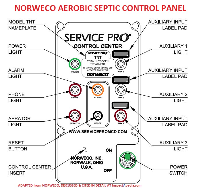
Aerobic Septic System Alarm Faqs Q A On The Alarm Light Or Tone On Aerobic Septic System Controls
Sump Sewage Applications Choosing 3 Float Vs 4 Float Control
Tank Alert Ez Alarm Avloppscenter

Pumps In Dosing Systems Onsite Installer

Simple Pump Controller And Circuit 13 Steps With Pictures Instructables

Learning Management System Sewage Ejector Pump Sump Pump Installation Sump Pump

Septic Pump Three Floats Youtube
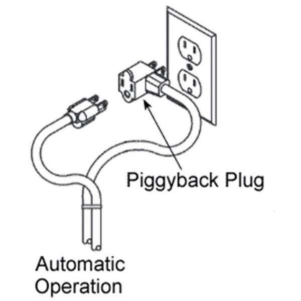
10 Ft Piggyback Float Switch Cable Septic System Sump Pump Water Tank 5 Year Warranty Mercury Free Visible In Water Sa 3100 3 The Home Depot

How Septic Systems Work King County
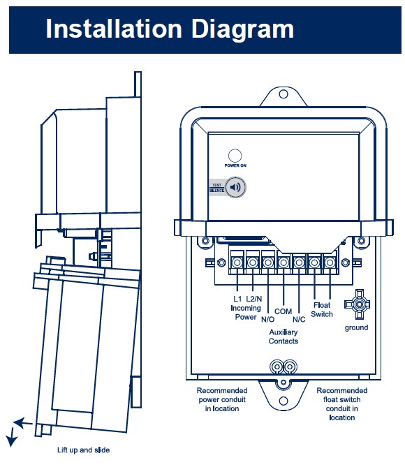
Wiring Diagrams Of Tricel Wastewater Treatment Solutions

Float Switch Installation Wiring Control Diagrams Apg